Frustrations With E3D's Revo Voron PZ Probe
I recently gave away my beloved Ender 3 to my friend. I had spent too much time fixing and refixing and calibrating and recalibrating it just for it to give me mediocre prints – it was taking too much time out of my life and I just couldn’t keep up. So, I decided to downsize to a smaller, simpler printer – the KP3S.
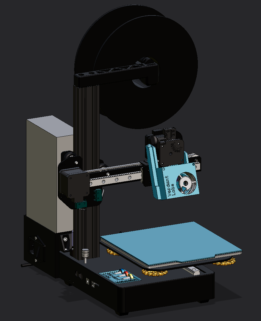
And it’s a pretty good little machine. I installed the Revo Voron PZ Probe that I had planned to install in the Ender. It promises perfect first layers, all the time, and the youtube videos I watched on it said the same. And that was my experience too! For the first 2 prints – then it became a nightmare.
Bad First Impressions
Right off the gate, deciding to order it was a TERRIBLE experience. E3D’s website is all sorts of broken. Right off the gate, trying to go to the revo section of their website is just straight up broken – it just brings me right back to the home page. This is clearly not intended behavior because every other page has a nice sub page for that product category. I thought revo was their flagship nozzle?
Firefox, Firefox mobile, Chrome, Chrome mobile, Zen browser – all broken. Windows, Linux and Android.
Ok, whatever. Googling PZ Probe gets me directly to the product page. As with any DIY thing, it’s important to read all the info before you know what you’re getting into. It even says to read the datasheet before installing – good advice!
Huh. Ok, well, E3D has been in the printer game a long time, and there’s a ton of reviews saying it’s good, so I gave them a pass and ordered it anyway. It seems pretty painless, and especially since they tout that
With PZ Probe you only need to calibrate your z offset once to accommodate for flexibility in your motion system, after that simply screw in (with only your fingers) a new nozzle, and PZ Probe does all the hard work for you…. Easy PZ!
it should be pretty painless, right?
Installation
It says on the website that it’s designed for the stealthburner, and since I was not using one of those, I can’t get mad that I couldn’t find designs I could use for my own printer right off the gate. What I am mad about is that the reference CAD that they give here is incomplete! My other V6 revo model has the heater sitting flush against the heatsink, so I assumed that it was the same for this. Not the case! Apparently the heatbreak section of the nozzle sits outside the heatsink a little, leading to my designs before I got the thing in the mail being totally wrong! I had to adjust it using the original non-pz revo voron hotend in my designs, something I was unsure of because I don’t know if they are the same measurements (datasheet isn’t there!). Also, why even give me the CAD for the coldside without the spring and hotside attached? Those are integral parts of the entire assembly! Even the dimensions on the wiki don’t show this! Speaking of which…
Awful Documentation & Product Flaws
I originally had these as two different sections, but each exacerbates the other so much that they felt too intertwined to separate.
The wiki has so many holes through it that really sealed the bow on the package that is the probe. On it’s surface, it’s pretty lengthy and in depth, but looking for information once I actually got the product showed some glaring holes. Probably the first thing to tweak after installation is which preset to use. So, naturally, I go to the preset section, which gives me this chart.
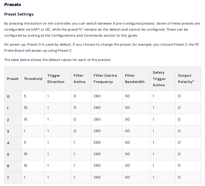
This actually gives me no useful information as an end user, other than maybe the output polarity. All I see is that the filter is active for half of them, and an arbitrary threshold value. The chart that I ACTUALLY want is not here, but at the top, in the features section, for some reason.
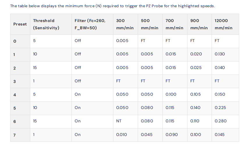
Ok, this is useful, except the speeds are given in mm/min? Why? I’ve never seen that anywhere in relation to printer speeds! Even in this very same wiki, other speeds are given in mm/sec!
During probing, reduce the current as much as possible without causing a stall. A good starting point is 40%, but lowering it further, if possible, will reduce the risk of damaging your bed. We have set our probing speed to 5 mm/s.
Very frustrating to have to divide the numbers by 60 for no reason. Also, Fc and F_BW aren’t explained in this chart – something that only makes sense reading the other chart first. A minor nitpick.
Ok, it’s fine, I eventually deciphered it. Set it to preset 4, since having a filter seems better than no filter, and… perfect! Benchy’s first layer, in ABS in an enclosure, worked perfectly. I do a few more tests, and, impressed with the results, I continue the other printing projects that I was doing, also in ABS. Since everything looked good, I shipped the print job, went to the other room, came back an hour later and…
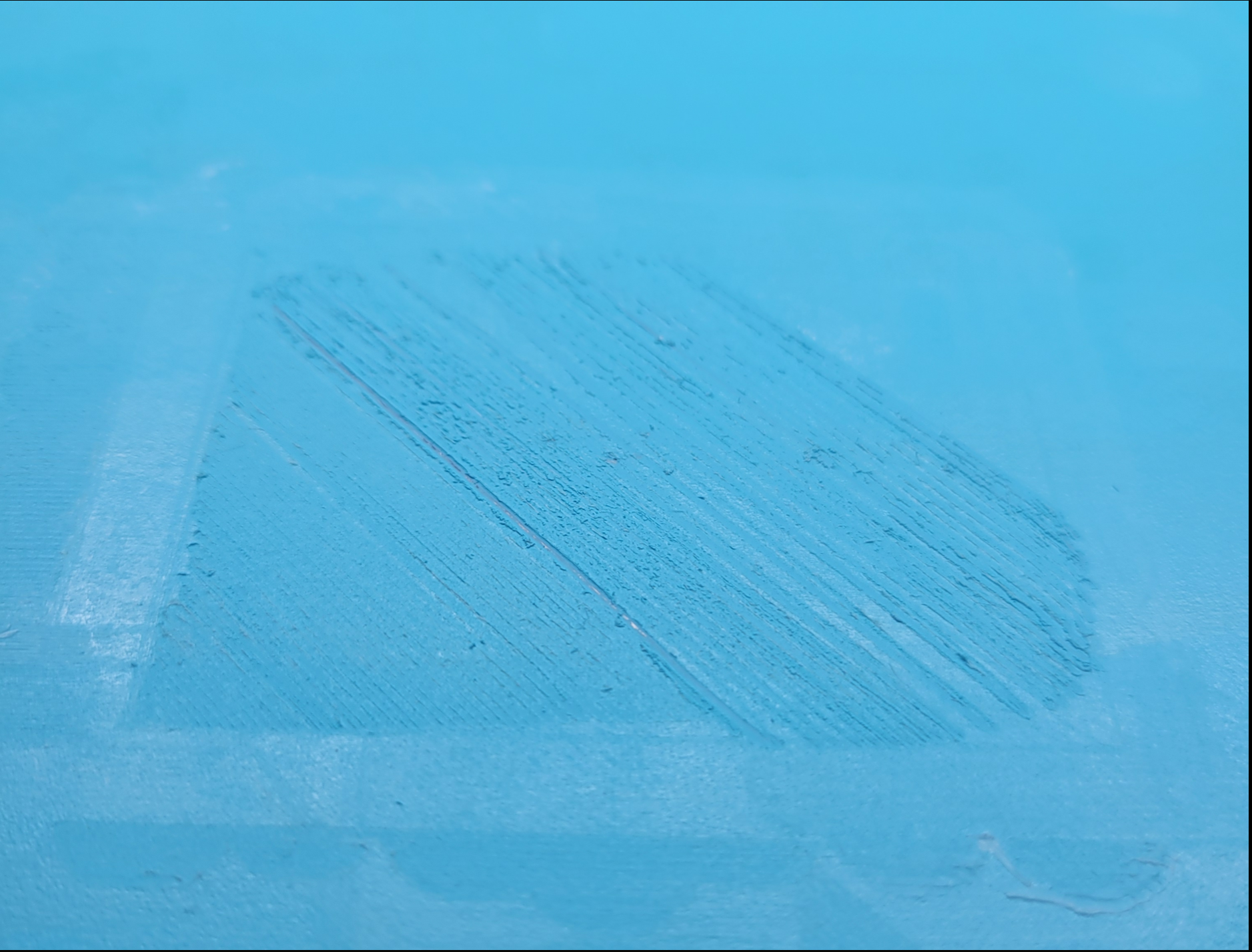
What happened! My brand new glacier build plate I got just for this machine, destroyed, dead center! And with my ObXidian 0.25mm nozzle – neither of those are cheap (the nozzle is seemingly undamaged, but still scary)! You can see the metal poking through! Sure, it’s my fault for not checking the first layer, but after a couple of hours of testing with no issues I figured that it would work just fine!
This is where the real headache began. I looked online for solutions, and one of the first things that popped up from other users is that the PZ Probe really benefits from having a rigid system, something my cantilever design doesn’t provide. Definitely a factor, but I assumed that since it worked, before, and since they say on the website it’ll work with flexible motion systems, I should be fine. Then, I found somewhere else that increase the speed could help compensate for the flexibility – that worked, kinda. A lot of accuracy was lost, and the magic perfect first layer didn’t work anymore, leading to the nozzle being really close to the bed and gouging out some more in different spots (my fault entirely). I thought that maybe the vibrations from the 3010 fan that I used for heatbreak cooling was the culprit, since that was tied on all the time and wasn’t a noctua, so I redesigned my entire toolhead to split the air stream from the 4020 noctua fan at the cost of printer speed – didn’t change anything. After DAYS of tweaking motor current, checking and rechecking wiring, running menial test after test, I found what I thought was the culprit – printing in an enclosure eventually brought the ambient temp too high to where the noise in the probe started to trigger false positives, which led to me doing higher thresholds, which led to nozzle crashes. At the same time, there seemed to be filter drift, since now any preset with the filter on is constantly triggered (except threshold = 1, for some reason), at room temp or saturated at ABS temp. It seemed that I had to set the filter myself, and I’ll do it via UART.
This is where the biggest headaches of the probe come to a head. I first checked which wires are the UART wires on the docs, labeled here:
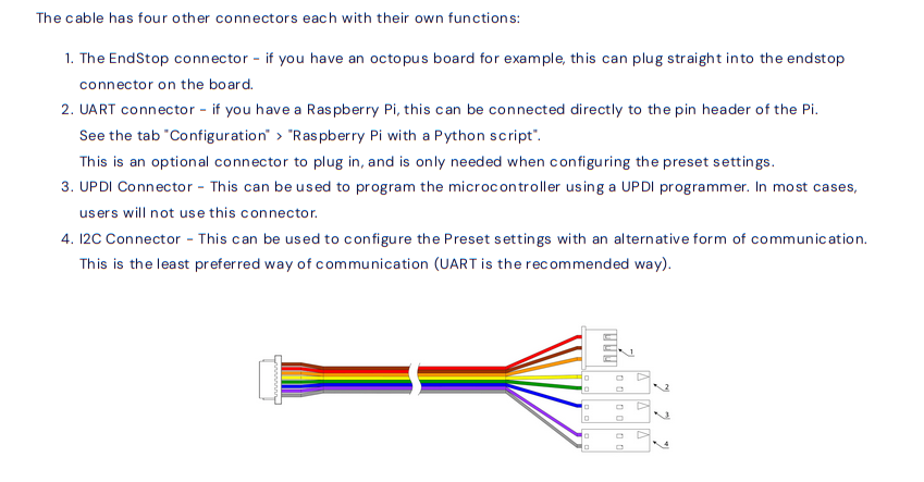
Ok, so I know that I need the yellow and green pins to talk to it. It doesn’t say which is TX and which is RX, but there’s only two wires, so not the biggest deal in the world (foreshadowing). The wiki says to use either an Arduino or an Raspberry Pi to communicate to it, neither of which I have (I run the printer with Klipper connected to my laptop with Klipper host in it’s own systemd container), but I have plenty of things to connect to it. I use my 3.3v USB-TTL to connect to it after a bunch of fiddling, and get readouts! It responds to button presses, but trying to send STATUS, or any of the other commands don’t work. I thought maybe it was an issue with my TTL, but no, loopback works fine. Continuity checks also are totally fine. I spend WAY too long fiddling with this, before switching to my ADALM2000 from college to try to connect to it. Issue is, the software isn’t packaged with NixOS, my linux distro. So I spend a few hours packaging the software for the ADALM2000 before I can even start debugging the damn thing. When I do, I spot something curious – the RX pin is a mirror of the TX pin! I think maybe that it’s cross talk of the wire, so I hook it up to the pins of the actual connector on the PCB with great difficulty, but no, the waveforms are identical whenever the probe is sending a message! I can’t imagine that this is a design issue because this couldn’t have gone through any QA, so I must have gotten a dud.
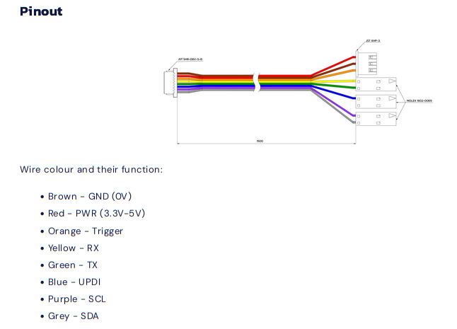
Ok, so UART is a bust. Luckily there’s a backup communication method, I2C. I don’t have any dedicated I2C devices, but I did a simple python script to do some bitbanging on the ADALM2000 to talk to it. Wiring this was a headache, since I2C has more pins that could be connected than UART, and the diagram earlier doesn’t show what pin is what. To find that, you need to scroll all the way to the bottom to get this diagram.
Why?! Why not just consolidate the diagrams! Why would this even be a different section! And even after wiring it, I have no idea what address to talk to! Running a scanner was slow, and turned up NOTHING! I just got some garbage from some random addresses, and have no idea which one to talk to. This should be documented! I spent so long just waiting for different iterations of speeds, addresses, pinouts, etc to complete just for it to turn up with NOTHING! If you’re gonna have I2C pins, why not DOCUMENT how to use them!!! And same with the UDPI connector – I don’t see ANYTHING on how to use it or how to update the firmware or nothing! And why isn’t the firmware open source so we can at least find the gaps in documentation! If there are licensing issues, fine, but information like this is critical.
It’s at this point where I gave up and started writing this blog post. Maybe if I persevered I could have eventually found the solution, but I hate reverse engineering things – the knowledge exists out there somewhere, and just isn’t being shared with me. Why should I work to re-achieve that knowledge?
Other complaints / thoughts
- There should be a calibration mode on the base firmware that writes the filter presets with the measured frequencies. Like you hold the button and it calibrates.
- There is no diagram of the entire assembly like there is on the revo voron page! You guys are clearly not against copying the same info to different pages (pz probe and pz standalone), why not this vital info? I don’t know if they are the exact same dimensions!
- Is there a way to remove the probe and replace it in case the cable tears? The exploded view in marketing materials makes me think so, as well as the keyed part of the filament path, but I can’t seem to figure it out.
- The lights, other than power light, should have a timeout so it’s not just blasting green light all the time. Once I set the preset, ideally I don’t need to know what preset I’m on anymore.
- Binary LEDs are annoying to look at with astigmatism / through the blurry clear plastic of my enclosure – it turned into a smear of green. It should either be differently colored binary lights, or just one RGB LED with different colors per profile.
- You guys should make a klipper macro / more firmware features that take advantage of the probe. One thought that I had was to sense if the probe is triggered for more than 2 seconds during an active print, and cancel it if it is. This would have pretty easily prevented my bed crashing issue.
- For this price point I expect flawless experience – I shouldn’t even need to contact customer service. This feels like a 10 dollar aliexpress product I’m hacking together – I could have gotten a much better experience for a fraction of the cost. I bought this thinking this was a buy once cry once type of thing.
Conclusion
I can’t recommend this product. If you’re looking for a piezoelectric probe, look at other projects. I have sent this to E3D’s support team to see if my problems are largely user error, but I doubt it.